The participants of the CCOM 4086 Computer Architecture I course, Fall semester, 2012:
In the Fall semester 2012 Humberto Ortiz-Zuazaga taught Computer Architecture I, and asked the students to work on implementing an 16 bit CPU in Logisim. Let's see if I finally got the spec right.
I first gave a design for a 16-bit CPU in my 2004 Computer Architecture course. The specification is described in this final exam.
The idea is to build a simple CPU up from logic gates. I asked students to use only and gates, or gates or inverters. I used RAM for the program memory, but we built everything else up.
The CPU will execute 16-bit instructions.
With 16 registers we can let 4 bits represent the rs, rt and rd registers, and have 4 bits for the op:
| 0000 | add | R format |
| 0001 | sub | R format |
| 0010 | lw | R format |
| 0011 | sw | R format |
| 0100 | and | R format |
| 0101 | or | R format |
| 0110 | not | R format |
| 1000 | addi | I format |
| 1001 | ldhi | I format |
| 1010 | bz | I format |
| 1011 | bnz | I format |
| 1111 | j | J format |
lwand
swcompute the target address as rs+rt.
ldhiloads an 8-bit immediate into the upper 8 bits of a register.
bzjumps to PC + imm8.
jjumps to PC + imm12.
With the format described above we can write a small program to count to n in 16-bit pseudoMIPS assembly
        add $1, $0, $0
	addi $1, 10          ; set n to 10
	add $2, $0, $0       ; set i to 0

loop:
	addi $2,  1
	addi $1,  -1
	bnz $1, loop         ; loop is PC-2
We can translate this by hand to the machine language:
             binary |  hex
0000 0001 0000 0000 | 0100
1000 0001 0000 1010 | 810A
0000 0010 0000 0000 | 0200
1000 0010 0000 0001 | 8201
1000 0001 1111 1111 | 81FF
1011 0001 1111 1110 | B1FE
Loading the instruction memory with these values will allow us to simulate the execution of the program.
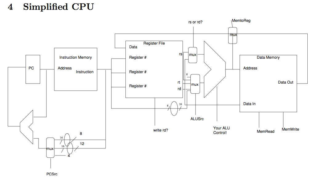
The design is a simplified version of the MIPS design presented in the textbook David A Patterson, John L Hennessy, Computer Organization and Design, Fourth Edition: The Hardware/Software Interface, 2009. ISBN 978-0-12-374493-7
A register file with 16 16-bit registers feeds into a simple ALU. We use multiplexers, decoders and demultiplexers to select the registers for the ALU to process. A control table drives the components based on the instruction to be executed.
Here are documents describing the design of some old 8-bit component:
Students are posting implementation pieces on the course forum, and can use the forum or piazza to coordinate. Once the implementation is complete, I'll post a version here.
This program is free software: you can redistribute it and/or modify it under the terms of the GNU General Public License as published by the Free Software Foundation, either version 3 of the License, or (at your option) any later version.
This program is distributed in the hope that it will be useful, but WITHOUT ANY WARRANTY; without even the implied warranty of MERCHANTABILITY or FITNESS FOR A PARTICULAR PURPOSE. See the GNU General Public License for more details.
You should have received a copy of the GNU General Public License along with this program. If not, see http://www.gnu.org/licenses/.

Most recent change: 2012/11/12 at 16:03
Generated with GTML